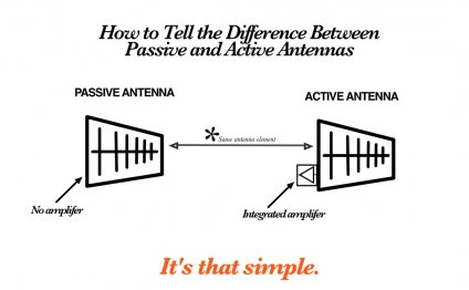
What is an Amplified Antenna?
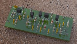 The following receiving amplifier can be used for any kind of signal in the HF and VHF bands from about 1 MHz to 400 MHz. It offers quite linear gain across this band width without using any LC tuned circuits. The circuit does not use coils. However, a choke will be required if you will power the amplifier through the feed cable.
The amplifier's input is unbalanced and it can be connected to any kind of antenna (after the balun if it is necessary). Because Q5 is placed in a common base configuration, the input impedance is high, thus the amplifier can be used with whip antennas too (they usually have high impedance at low frequencies). The output is 75 ohms unbalanced. The overall gain of this amplifier is 20 dB.
Here is the schematic of the amplifier. All capacitors are ceramic disc type. L1 RF choke can be omitted if you want to power the amplifier from a separate power supply.
Amplifier schematic
It can be built on a single sided PCB of 32 x 76 mm. The PCB should be enclosed in a metal case and the entire amplifier should be mounted near the antenna. This is the component outline on PCB:Component outline
The amplifier is powered from 6...12 V. The gain is about 20 dB.Gain is 20dB
Downloads: PCB as PDF | ExpressPCB and LTspice filesBased on an article from Romanian electronics magazine "Tehnium".
RELATED VIDEO


Share this Post
Related posts
What is an OTA antenna?
While cordcutting articles often focus on people eliminating cable, there are just as many people nervous to ditch their…
Read MoreWhat is an off air antenna?
An off-air antenna is an item folks use to receive over-the-air signals from broadcast television channels. In order to use…
Read More

