TV Aerial Connection Diagram
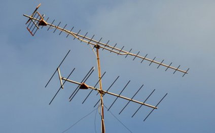
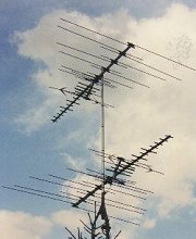 By combining two television antennas collectively, you'll be able to receive TV programs in two various instructions without requiring the application of an antenna rotator. This kind of set up can be carried out successfully, but appropriate spacing needs to be held amongst the two antennas to assist avoid the antennas from interfering with one another and causing ghosting on television picture.
The formula for determining the minimal straight spacing involving the two antenna booms is a half l (trend) associated with the least expensive station becoming received. To calculate this length just take 467 and divide it by the cheapest television channel regularity that'll be gotten by either of two antennas. So for example, if the cheapest channel gotten by either associated with the two antennas is channel 2, you'll take 467 and divide it by the reduced frequency of channel 2 (54 MHz). This will give you the minimum vertical spacing of 8.64 legs or 103.7 ins that might be required involving the two antenna booms.
If two antennas will likely to be spaced aside horizontally (such as for instance in an attic) it is strongly recommended which they be divided by 1 wavelength as opposed to a half wavelength as with straight spacing.
There must become very same length of coaxial cable between the two antennas as well as the combiner, which is fundamentally a backwards two-way signal splitter. Equivalent exact period of coax cable between each of the two antennas plus the combiner is needed and to help alleviate problems with ghosting from occuring on TV's attached to the antenna system.
Even although you correctly separate the 2 antenna together and possess equal lengths of coaxial cable you can easily run into dilemmas. The greatest problem is whenever the two antennas begins to receive the station(s) inside opposite way (through the back) that it is directed. This could easily create ghosting on the TV's attached. To reduce or expel this issue in domestic antenna systems, bandpass filters and station traps are employed.
A relatively inexpensive bandpass filter/channel trap could be the Channel Master JOIN-TENNA coupler. The JOIN-TENNA coupler has two 75 Ohm coax cable inputs and another 75 Ohm coax cable result. Among the two inputs is connected to a bandpass filter that lets only the solitary specified channel through. One other feedback is connected to a channel pitfall to filter out the solitary channel while driving other channels. By just letting the single channel through one feedback and trapping it associated with the other input, the actual quantity of disturbance is paid down.
The JOIN-TENNA coupler model is chosen because of the solitary station which you desire to combine with every one of the other channels. The JOIN-TENNA coupler can't be always combine adjacent stations, excluding channels 4 and 5, and channels 6 and 7. The JOIN-TENNA coupler can also be used as a -20dB solitary channel trap. Make sure not to ever capture channels ajacent into the ones that you need. For more information on how-to connect the JOIN-TENNA coupler understand connection drawing under.
RELATED VIDEO
Share this Post
Related posts
UHF Aerial connection
The modest Belling-Lee UHF connect is popular in European countries as a television and FM connector, popularly known as…
Read MoreTV Aerial Erectors
Tel: 59 Areas served: Barnard Castle, Bedale, Billingham, and 33 other people. York Aerial Erectors Tel: 30 Areas served:…
Read More
